
1.The Hidden Culprit—Thermal Growth & Machine Deflection
The Issue
When your rotary table runs for extended periods, heat generation from bearings, motors, and friction causes thermal expansion. This isn’t uniform expansion—different materials and components heat at different rates, causing the table to “grow” unpredictably. A table that’s perfectly calibrated at 8 AM can be 0.02mm off by noon, with errors that aren’t linear and therefore impossible to compensate for with simple tool offsets.
How to Identify It
- Parts machined in the morning vs. afternoon show consistent dimensional drift
- Accuracy degrades during long continuous cuts but seems fine for short operations
- Touch probes give different readings at the start vs. end of a job
Practical Solutions
Monitor Environment: Maintain consistent shop temperature (±2°C variation maximum)
Implement Warm-Up Protocols: Run the rotary table through its full range of motion for 10-15 minutes before critical work
Use Temperature-Stable Tables: Invest in tables with built-in cooling systems or thermal compensation (like Autocam’s temperature-monitored models)
Schedule Smartly: Place tight-tolerance operations consistently at the same time of day
2.The Silent Killer—Poor Workholding & Fixture Flex
The Issue
A 4th axis table is only as rigid as its weakest connection point. Many machinists focus on table specs while neglecting that their fixturing system flexes under cutting forces. This flex isn’t constant—it varies with the rotational position, creating errors that appear random but follow predictable physical laws.
Real-World Example
When machining aluminum aerospace brackets, a shop found ±0.15mm variations. The problem wasn’t the $50,000 rotary table—it was the $800 chuck flexing. At certain angles, cutting forces created a lever arm that the chuck couldn’t resist.
Fixturing Checklist
- Chuck Selection: Use through-hole chucks with maximum gripping surface
- Support Distance: Keep workpieces as close to the chuck face as possible
- Tailstock Alignment: For long parts, ensure perfect tailstock concentricity
- Custom Fixtures: For production runs, invest in dedicated fixtures rather than universal chucks
Quick Test
Mount a test bar and indicate runout at various rotational positions while applying moderate hand pressure. If runout changes more than 0.01mm, your fixturing needs improvement.
3. The Programming Pitfall—CAM/Post-Processor Mismatch
The Issue
Your CAM software might show perfect toolpaths, but if the post-processor doesn’t account for your specific table’s kinematics, you’ll get mathematically correct but physically wrong movements. Common issues include:
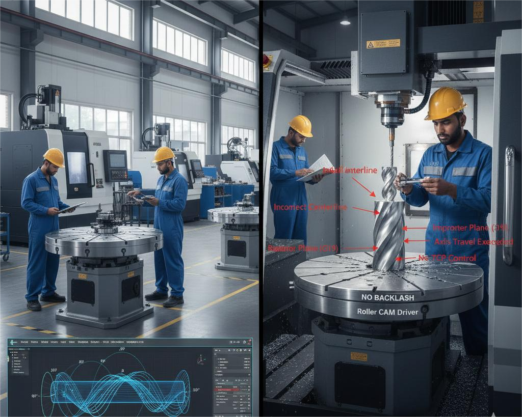
- Incorrect centerline programming
- Improper plane selection (G17, G18, G19)
- Missing or wrong rotary axis limits in the post
- Improper handling of tool center point (TCP) control
Solution Framework
- Post-Processor Verification Checklist:
| What to Check | Why It Matters | Test Method |
|---|---|---|
| Rotary Centerline | Off-center programming ruins cylindrical features | Machine a test sphere; measure roundness |
| Axis Limits | Prevents crashes and maintains optimal orientation | Command moves beyond limits; verify soft limits work |
| G-Code Output | Ensures proper G93 (inverse time) or G94 (units/min) usage | Compare posted code to machine manual requirements |
| Error Handling | Proper response to overt travel situations | Test near limit conditions |
- Proven Testing Protocol:
- Test 1: Machine a simple cylinder, measure diameter at multiple heights
- Test 2: Mill a spiral groove with constant depth, verify consistency
- Test 3: Create a part with features at 0°, 90°, 180°, 270° positions
4. The Maintenance Oversight—Backlash Accumulation
The Issue
Backlash isn’t binary—it accumulates and worsens over time. Many shops check backlash annually, but wear happens continuously. The dangerous assumption is that “the table worked fine last month.”
Proactive Maintenance Schedule
Daily:
- Visual inspection for chips/debris in the rotary mechanism
- Listen for unusual sounds during rotation
Weekly:
- Check lubrication levels
- Verify home position repeatability
Monthly:
- Perform backlash check using dial indicator method
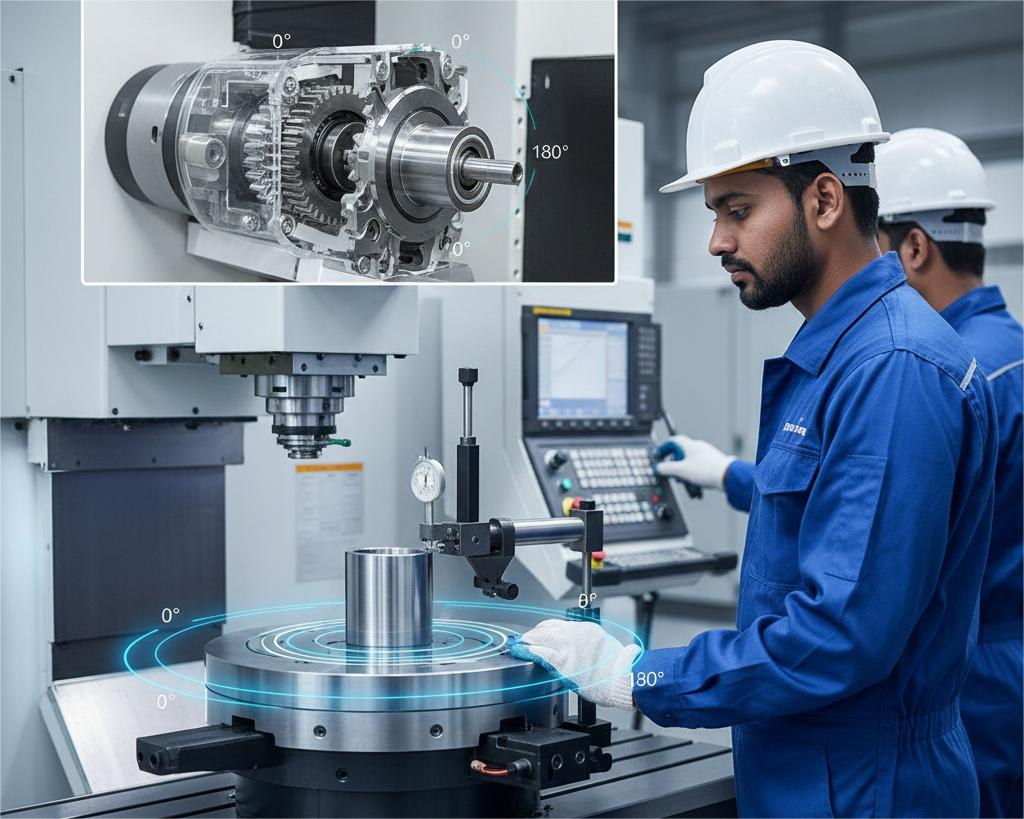
- Test positioning accuracy at 4 quadrants (0°, 90°, 180°, 270°)
Quarterly:
- Full calibration against master square/sphere
- Bearing pre-load check
- Motor coupling inspection
The Backlash Test Simplified
- Mount a dial indicator touching a test fixture
- Command small moves in one direction (e.g., 1° increments)
- Reverse direction and note movement before indicator moves
- Repeat at multiple positions around the table
Acceptable Limits:
- Precision work: < 0.001° (6 arc-seconds)
- General work: < 0.005° (30 arc-seconds)
- Action Required: > 0.01° (60 arc-seconds)
5.The Setup Error—Incorrect Centerline Alignment
The Issue
The most fundamental yet commonly botched setup: ensuring the rotational centerline perfectly aligns with the machine’s coordinate system. Even 0.02mm misalignment causes 0.04mm error in diameter, and this error compounds with part length.
Foolproof Alignment Method
Step 1: Rough Alignment
- Use a coaxial indicator in the spindle
- Indicate the table’s center bore or a precision mandrel
- Adjust until runout < 0.02mm
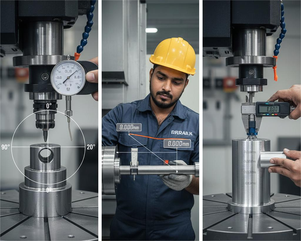
Step 2: Fine Alignment (Sweep Method)
- Mount a test bar with known precision
- Sweep indicator at two positions along the bar (near and far)
- Adjust until both positions show identical readings
- Target: < 0.005mm TIR at furthest point
Step 3: Verification Cut
- Machine a test cylinder
- Measure at multiple positions
- If diameter varies, misalignment persists
Achieving consistent 4th axis machining accuracy is essential for producing high-quality, precision components, yet many CNC shops face avoidable challenges during multi-axis operations. Common issues such as CNC rotary table backlash, improper setup, and wear over time can directly impact dimensional accuracy and surface finish. A poorly followed 4th axis alignment procedure or irregular rotary table calibration often leads to indexing errors, vibration, and repeatability problems—typical multi-axis machining problems seen in day-to-day production.
In addition, inadequate lubrication and missed inspections highlight the importance of a structured CNC rotary table maintenance checklist to maintain long-term performance. Factors like incorrect cutting parameters and mechanical play can also affect tool engagement, making improving 4th axis surface finish a frequent concern for manufacturers. By understanding proven backlash compensation methods, along with proper alignment, calibration, and preventive maintenance practices, machinists can significantly reduce errors, enhance part quality, and fully utilize the capabilities of their 4th axis CNC rotary table.